| |
《包装设计制作工艺与检测技术标准实用手册》
第四篇 包装设计基础
第三章 包装容器结构设计
第四节 金属包装容器结构设计
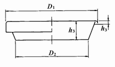
图4-3-156 开口钢桶顶盖结构尺寸

图4-3-157 开口缩颈钢桶结构尺寸
表4-3-42 全开口钢桶结构尺寸,mm
结构尺寸\公称容量/L |
200 |
100 |
80 |
50 |
35① |
25 |
极限偏差 |
桶内径d |
560 |
430 |
415 |
385 |
330 |
285 |
±2 |
桶内高H |
850 |
720 |
615 |
450 |
430 |
410 |
±3 |
环筋高A |
14 |
10 |
8 |
- |
- |
- |
±2 |
环筋间距L |
280 |
280 |
210 |
- |
- |
- |
±3 |
波纹高B |
3 |
2 |
2 |
2 |
2 |
2 |
±1 |
桶底高h1 |
19 |
16 |
16 |
12 |
12 |
12 |
±1 |
桶盖深h2 |
21 |
16 |
16 |
12 |
12 |
12 |
±2 |
桶盖边深h3 |
7 |
7 |
7 |
7 |
7 |
7 |
±1 |
卷管直径D |
10 |
8 |
8 |
6 |
6 |
6 |
±1 |
桶顶盖外径D1 |
585 |
451 |
436 |
402 |
347 |
302 |
±2 |
顶盖配合外径D2 |
557 |
427 |
412 |
382 |
327 |
282 |
±1 |
①是保留容量。
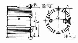
图4-3-158 小开口钢桶结构尺寸
表4-3-43 开口缩颈钢桶结构尺寸,mm
结构尺寸\公称容量/L |
100 |
80 |
63 |
45① |
35① |
25 |
极限偏差 |
桶内径d |
430 |
415 |
385 |
365 |
330 |
285 |
±2 |
缩颈内径d1 |
400 |
385 |
355 |
355 |
300 |
255 |
±2 |
桶内高H |
720 |
615 |
550 |
450 |
430 |
410 |
±3 |
波纹高B |
2 |
2 |
2 |
2 |
2 |
2 |
±1 |
桶底高h1 |
16 |
16 |
12 |
12 |
12 |
12 |
±1 |
桶盖深h2 |
16 |
16 |
12 |
12 |
12 |
12 |
±2 |
桶盖边深h3 |
7 |
7 |
7 |
7 |
7 |
7 |
±1 |
卷管直径D |
8 |
8 |
6 |
6 |
6 |
6 |
±1 |
桶顶盖外径D1 |
421 |
406 |
372 |
352 |
317 |
272 |
±2 |
顶盖配合外径D2 |
398 |
383 |
353 |
333 |
298 |
253 |
±1 |
①是保留容量
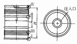
图4-3-159 中开口钢桶结构尺寸
表4-3-4 4小开口钢桶结构尺寸,mm
结构尺寸\公称容量/L |
200 |
100 |
80 |
50 |
20 |
极限偏差 |
桶内径d |
560 |
430 |
415 |
385 |
285 |
±2 |
桶内高H |
850 |
720 |
615 |
450 |
330 |
±3 |
环筋高A |
14 |
10 |
8 |
- |
- |
±2 |
环筋间距L |
280 |
280 |
210 |
- |
- |
±3 |
波纹高B |
3 |
2 |
2 |
2 |
2 |
±1 |
桶顶深h |
19 |
16① |
16① |
16① |
16① |
±1 |
桶底深h1 |
19 |
16① |
16① |
16① |
12 |
±1 |
注入口至卷边内侧距离L1 |
75 |
75 |
75 |
75 |
60 |
±2 |
注入口至透气孔中心距L2 |
415 |
290 |
265 |
235 |
165 |
±4 |
①若选用掀压式盖则为12mm。
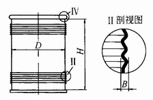
图4-3-160 固碱钢桶结构尺寸
表4-3-45 中开口钢桶结构尺寸,mm
结构尺寸\公称容量/L |
200 |
100 |
80 |
50 |
25 |
极限偏差 |
桶内径d |
560 |
430 |
415 |
385 |
285 |
±2 |
桶内高H |
850 |
720 |
615 |
450 |
410 |
±3 |
环筋高A |
14 |
10 |
8 |
- |
- |
±2 |
环筋间距L |
280 |
280 |
210 |
- |
- |
±3 |
波纹高B |
3 |
2 |
2 |
2 |
2 |
±1 |
桶顶深h |
19 |
16① |
16① |
16① |
16① |
±1 |
桶底深h1 |
19 |
16① |
16① |
16① |
12 |
±1 |
①若选用掀压式盖则为12mm。
返回目录页
|
|